Tanksline
TANKSLINE
Applications Tanksline columns and tanks can be employed in various processes, such as:
- washing
- destillation or rectification
- absorption columns for Hcl/Hbr, etc.
- liquid extraction
- reactors
- storage tanks
Material PropertiesPTFE is widely known for its excellent and universal anti-corrosion properties, which are only limited in case of media like certain alkali metals and special halogen mixes under harsh temperature conditions
ApplicationsThe application range of PTFE-lined columns is from -10°C to +200°C. However, under particularly harsh operating conditions such as those involving high and sudden pressure and temperature changes, or in case of special shapes, etc. these application limits become narrower. The maximum operating pressure is 6 bar; special engineering solutions must be studied for vacuum applications. The Tanksline PTFE lining is obtained from virgin materials which are then processed with particular techniques to guarantee high hydrophobicity and dimensional stability. The PTFE linings are available in thicknesses from 3 to 5 mm. The well-known non-stick properties of PTFE ensure high resistance to fouling and excellent cleanliness, as a result reducing or even eliminating downtimes. Columns and tanks are available in nominal diameters from DN 300 to 2000 in flanged sections up to 2 metres in height (depending on the DN), flat or taper end plates, welded or machined nozzles, along with a range of PTFE internals such as distributors, supports, rings, diffusers, suction tubes, etc. This catalogue describes the Tanksline® standard components in full details. We strongly recommend the use of standard parts so as to limit the number of eventual spares in the customer’s inventory. In case of certified and tested equipment, the use of standard PTFE-lined components allows the repair of the lining without the need for testing the metal substrate again.
ServicesDiflon Technology Srl offers a complete range of services:
- detail design according to current standards: ASME, PED, etc.
- manufacturing and testing under the control of certification bodies (ISPESL, TÜV, etc.)
- testing supervision..
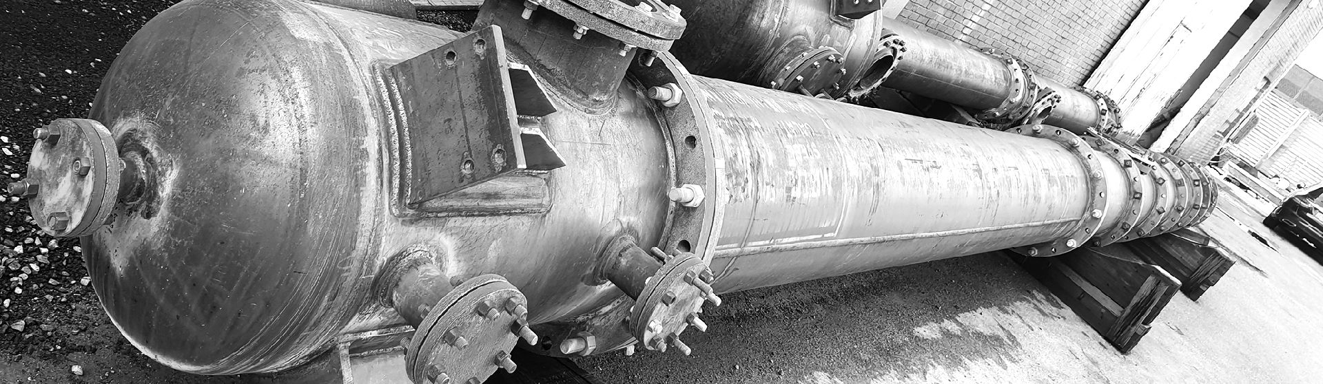
Column Lined Internally in Virgin PTFE SP 5mm
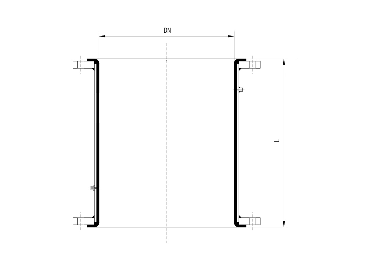
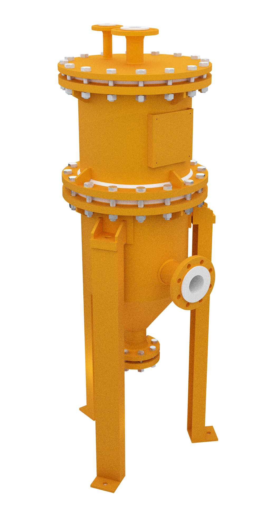
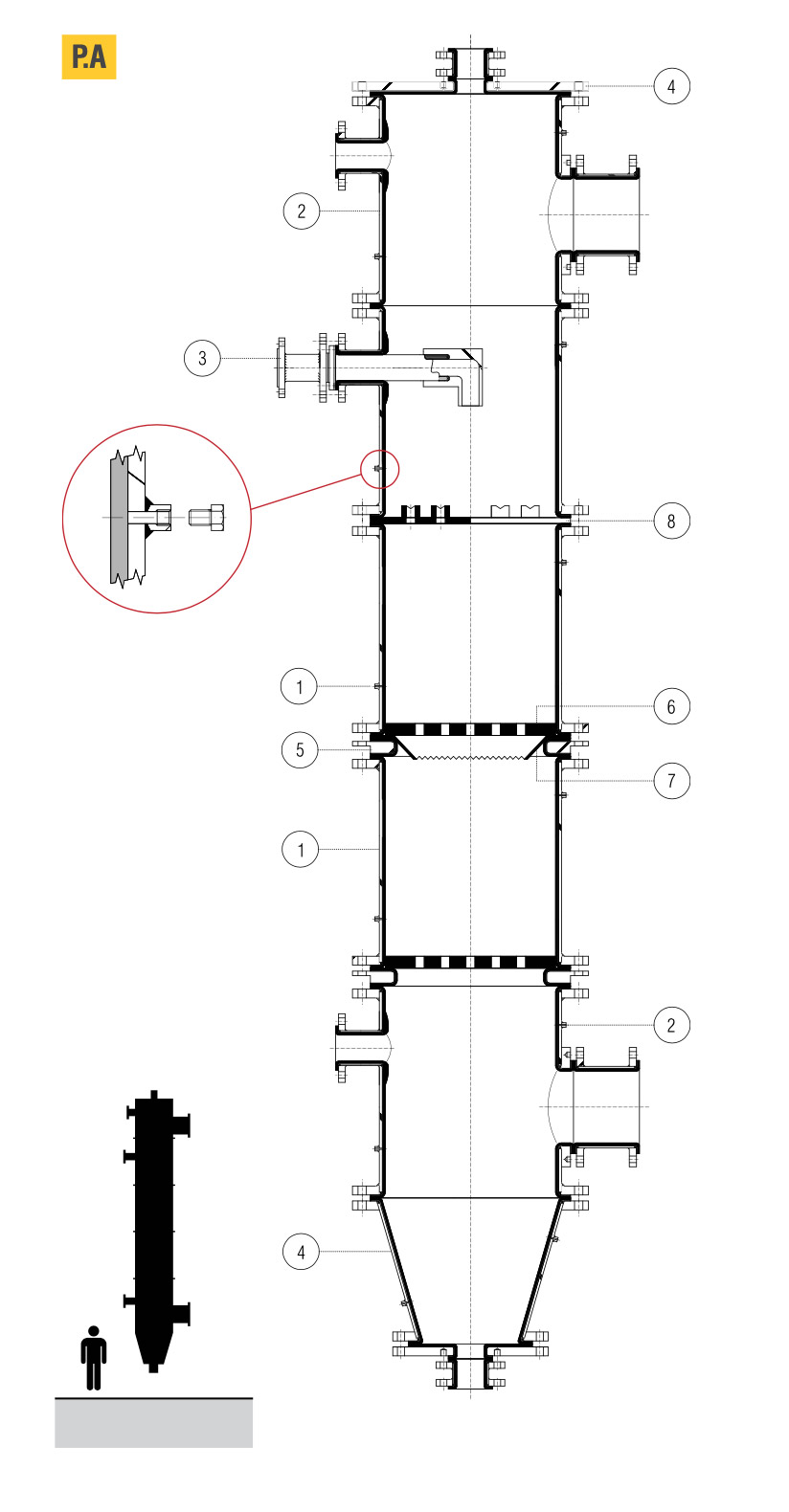
Column Lined Internally in Virgin PTFE SP 5MM
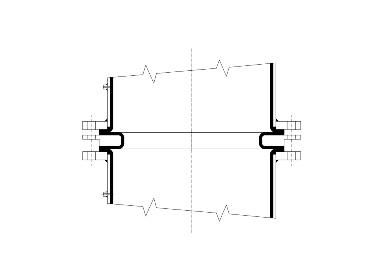
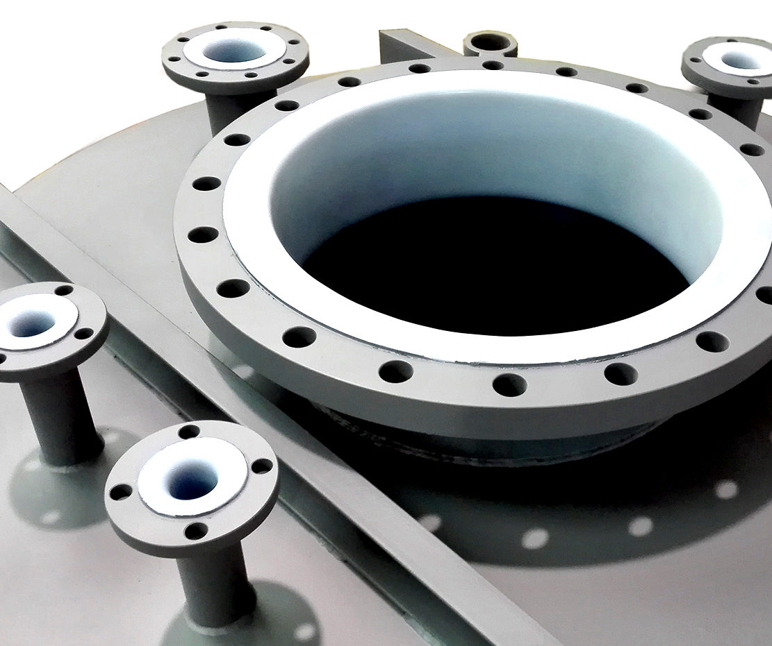
Maximum recommended outside diameter 2000 mm • Maximum height of column section ≤ DN 600L= 2000 mm; ≥ DN 700 up to 1200 mm. • Collet outlets are available for DN ≤ 100 directly welded on PTFE for DN ≥ 150 the outlet is directly obtained from the PTFE collet. • We recommend assembly with flat Ocean packing of variable sections, and tightening with torque wrench (see Diflon catalogue).
Key to the column’s components
•1 PTFE-lined column sections
• 2 Feed sections
• 3 Dip tubes
• 4 Flat or taper end plates
• 5 Grid support ring, caps, etc.
• 6 Support grid
• 7 PTFE redistributor
• 8 Distributor plate
• 9 PTFE-lined tank
Materials
Metal versions on customer’s request and/or specifications
PTFE ASTM D 4894
Auxiliaries
Tanksline columns and tanks can be equipped with support plates, PTFE-lined grids (even in Hastelloy steel), caps, perforated plates, support rings, injectors, anti-implosion systems, etc.
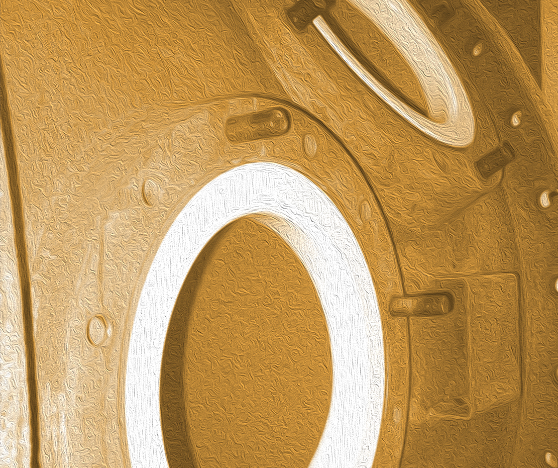
Vent holes for column sections and tanks PA
Each section incorporates a vent hole with minimum diameter of 3 mm, carrying out various functions:
• timely signalling of eventual leaks
• the elimination of air bubbles which form between the
metal substrate and the PTFE lining
• the possibility of vacuum connections.
N.B.
In case of hydraulic test on metal parts, the vent holes must be sealed. In case of external insulation the nipples must be extended with screwed-in tubes in order to come through the insulating layer. In case of stops of the implant in which the conditions of thermal excursions exist, the internal lining, not being anchored to the metal parts, can be moved from the sealing seats. In this case it is possible to restore, use a specific procedure by contacting our technical office.
Metal column section and tank with 5mm PTFE LINING Certificates and testing
- According to the current standards on metal components
- For the materials employed
- With scintillometer and 10,000 V on PTFE components
- Operating temperature -10°C +220°C
- Pressure +6 bar
- Vacuum resistance values up to DN 600
Materials
- Metal: on customer’s request
- PTFE: ASTMD4894 thickness 5 mm
| Ø |
L max. |
Vacuum |
SP PTFE mm |
| 400 |
4000 |
si/yes |
6,5 |
| 450 |
3500 |
si/yes |
6,5 |
| 500 |
2500 |
si/yes |
4,5 |
| 600 |
1200 |
si/yes |
5 |
| 800 |
1200 |
no* |
5 |
| 1000 |
1200 |
no* |
5 |
| 1200 |
1200 |
no* |
5 |
| 1400 |
1200 |
no* |
5 |
| 1600 |
1200 |
no* |
5 |
| 1800 |
1200 |
no* |
5 |
| 2000 |
1200 |
no* |
5 |
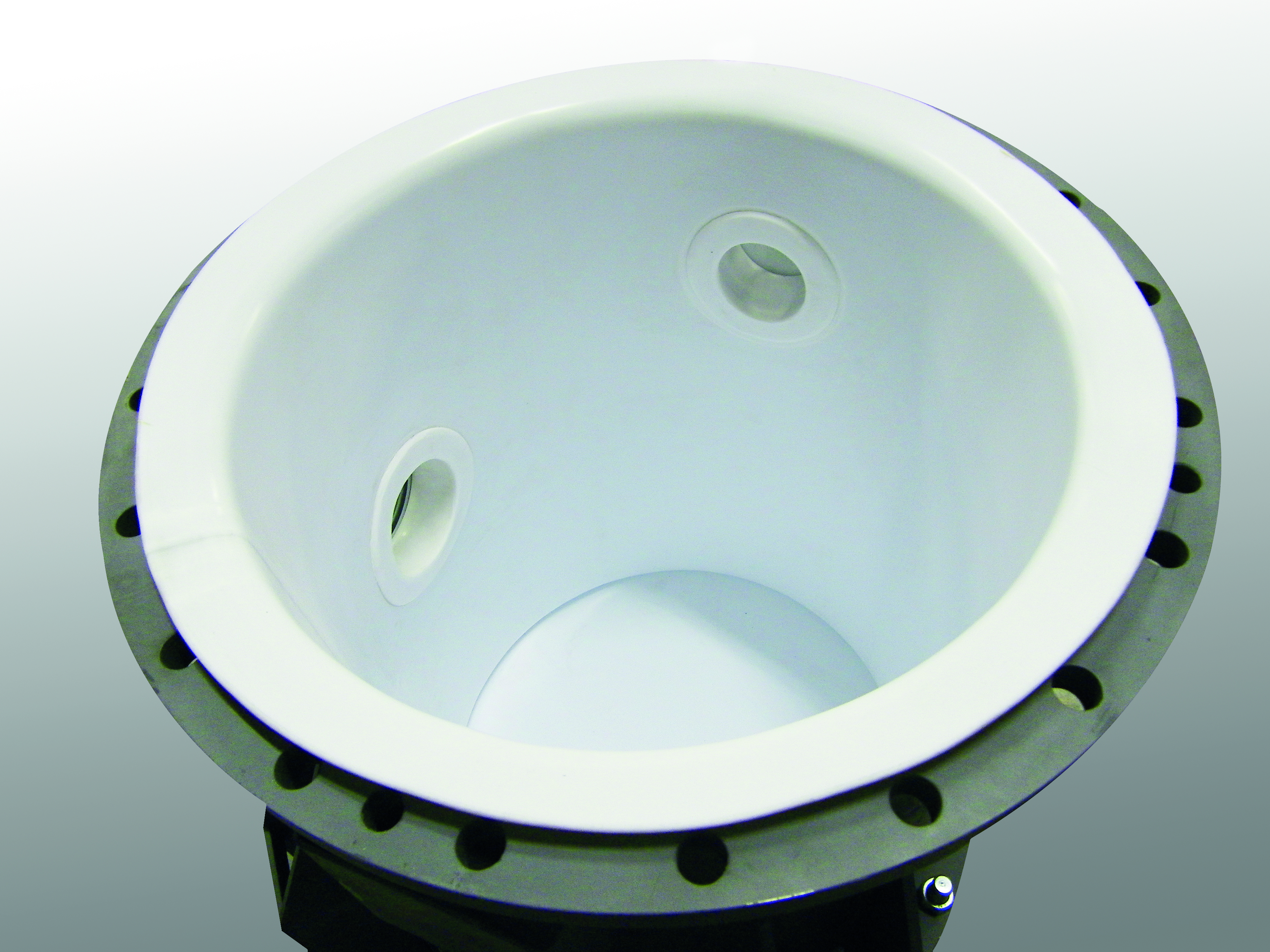
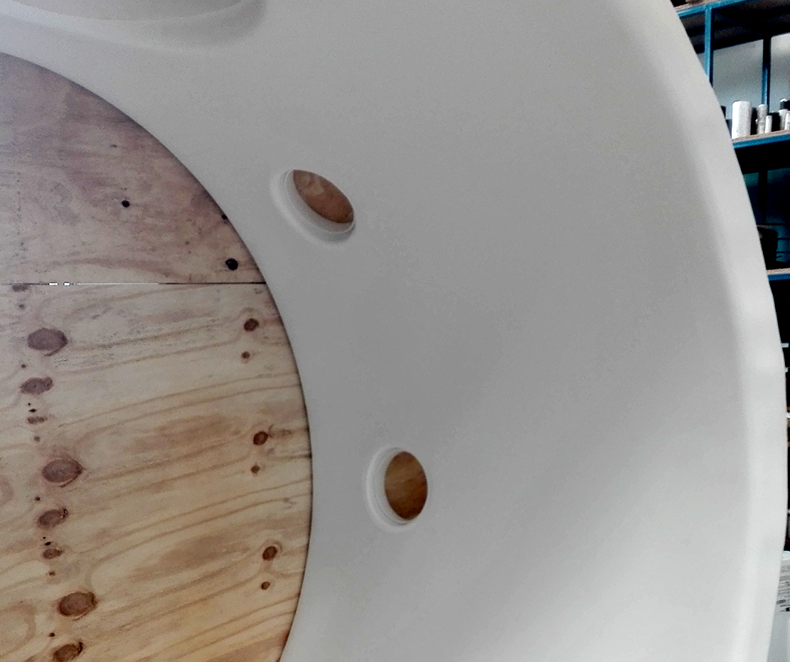
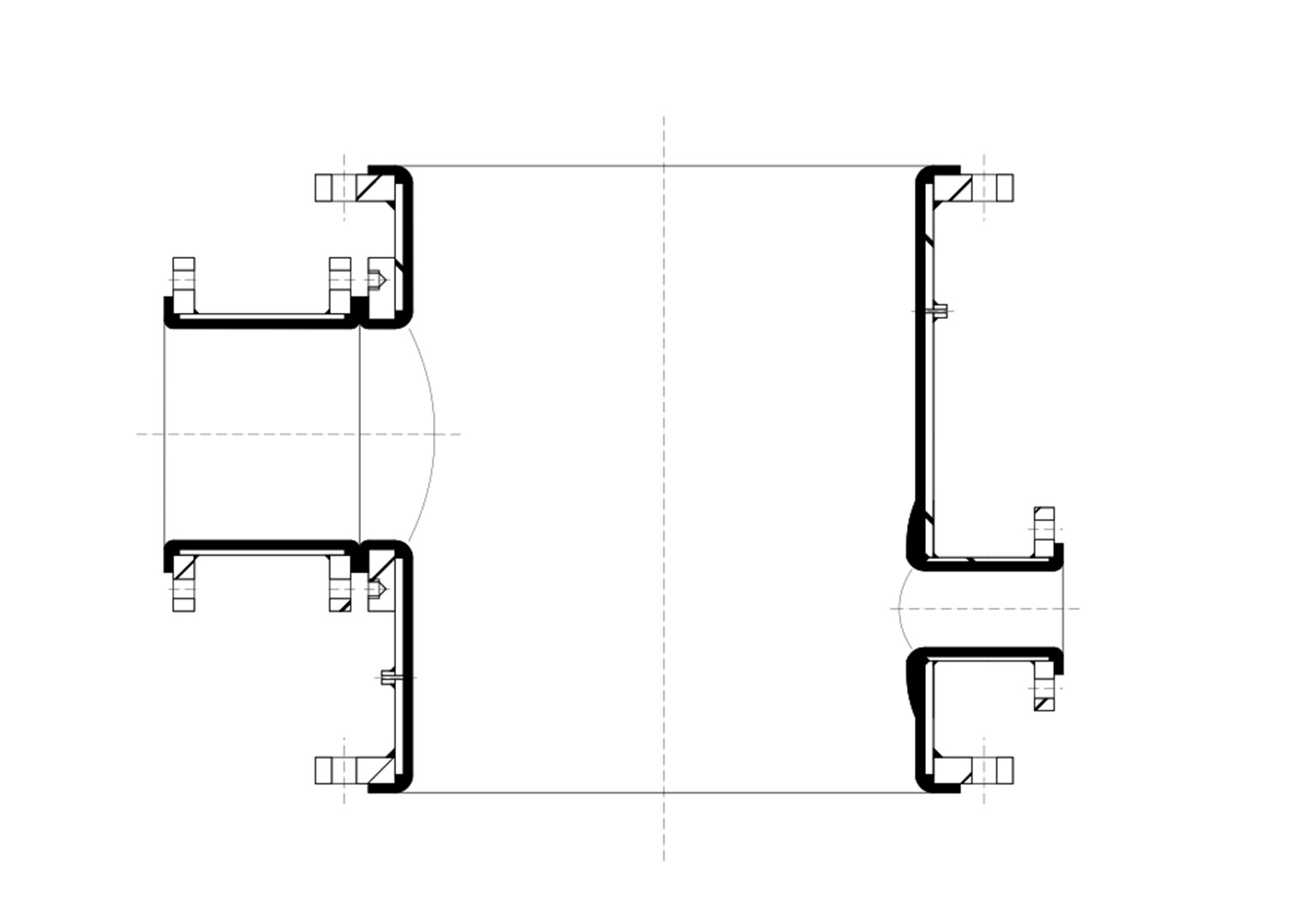
Free/drain columns section
These sections incorporate lateral nozzles, which can be welded on the column or directly obtained from the internal PTFE lining
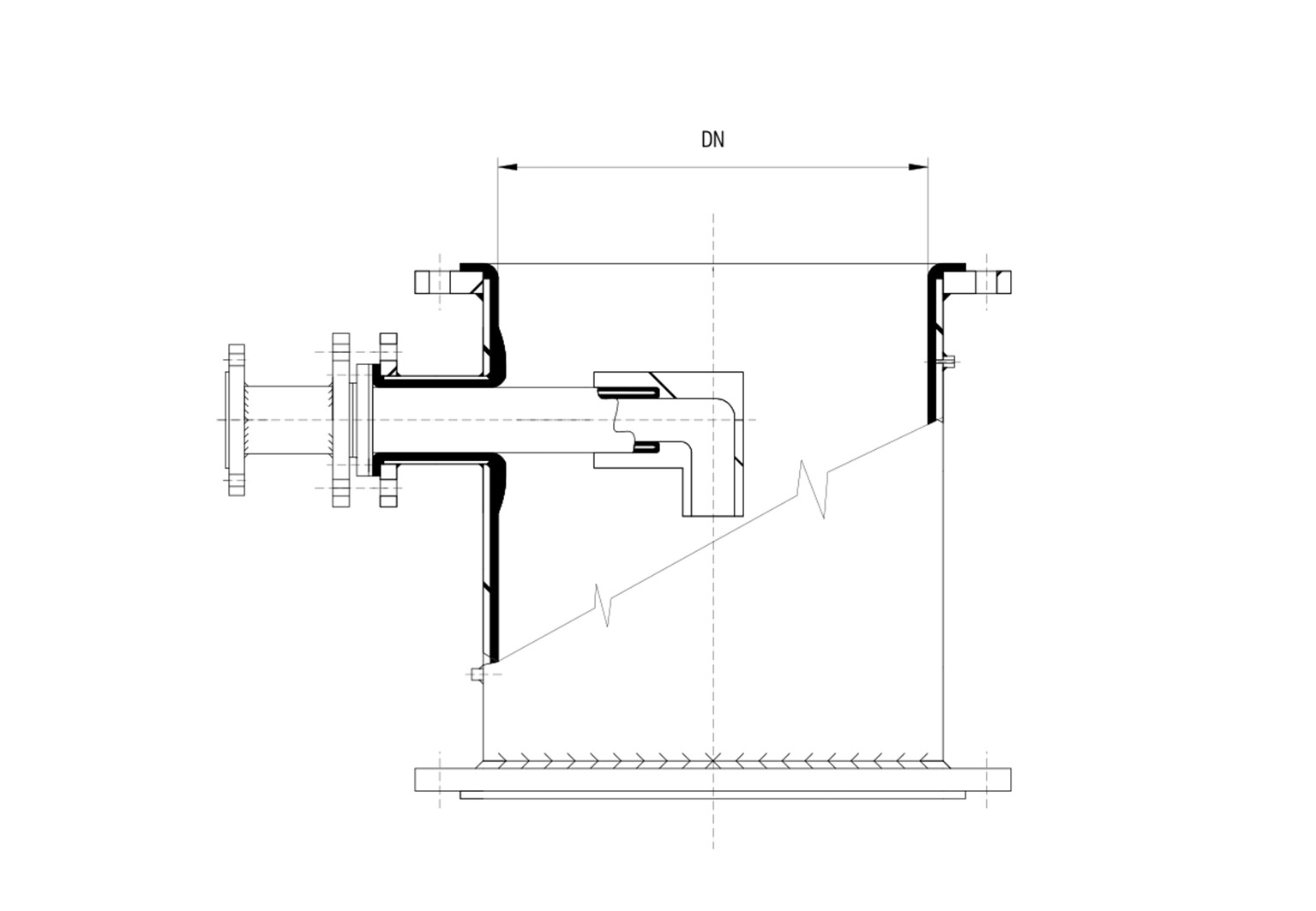
Steel dip tubes with internal and external PTFE lining
The dip tubes are used for feeding process media into the column. They are made of steel and have internal and external PTFE linings. The tube end has a screwed-in terminal piece for medium distribution. The dip tubes are also available in curved versions. Please contact our customer’s service for further information.
Steel dip tubes
The dip tubes are used for feeding process media into the column. They are made of steel and have internal and external PTFE linings. The tube end has a screwed-in terminal piece for medium distribution. The dip tubes are also available in curved versions. Please contact our customer’s service for further information.
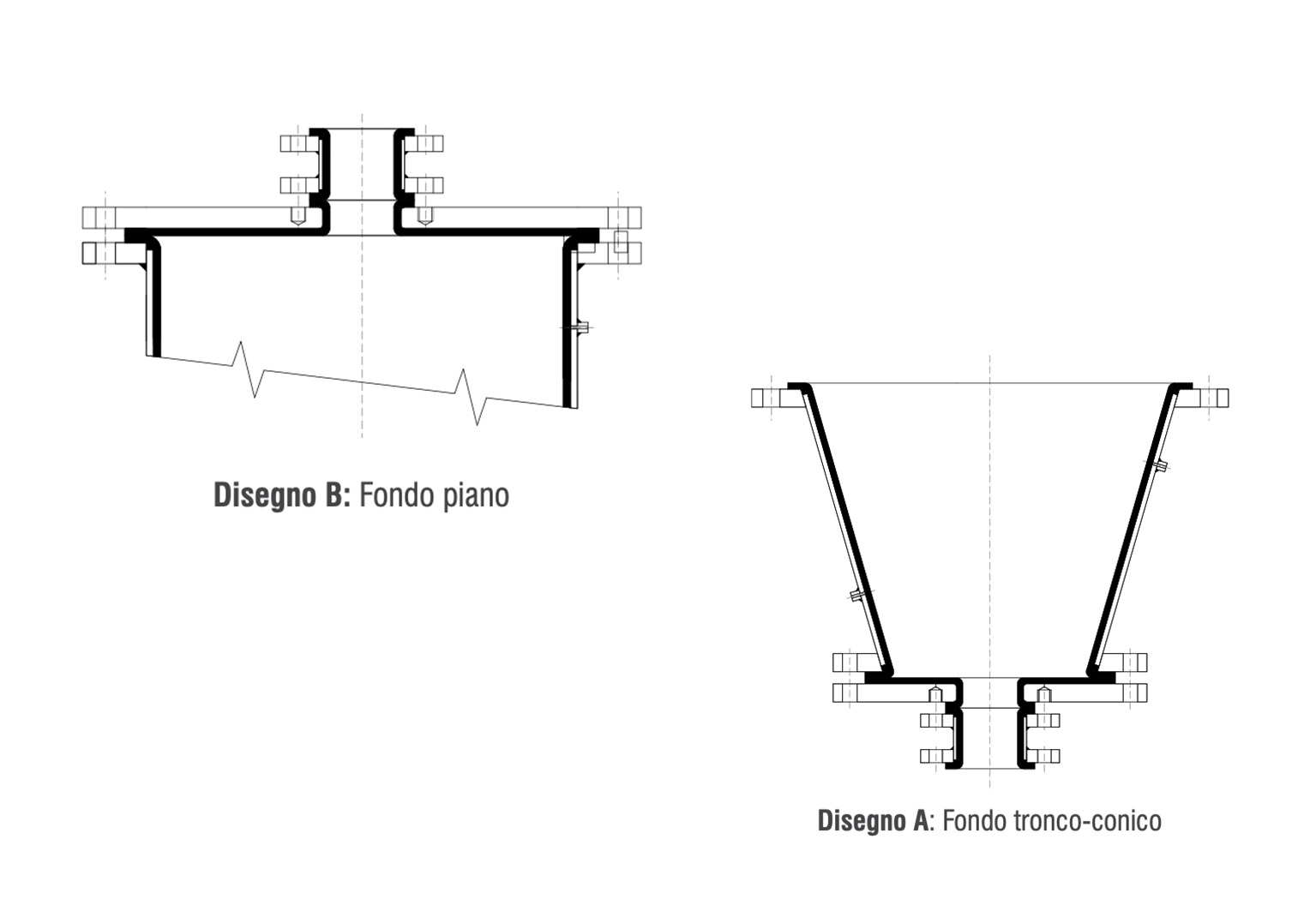
Flat and/or taper end plates
The use of end plates is recommended for sealing the top and the bottom sides of columns. The connections are dimensioned according to Diflon’s experience and to the equipment available.Of course, special versions can be also supplied on request. The bottom plates can be the taper (A) or flat (B) types.
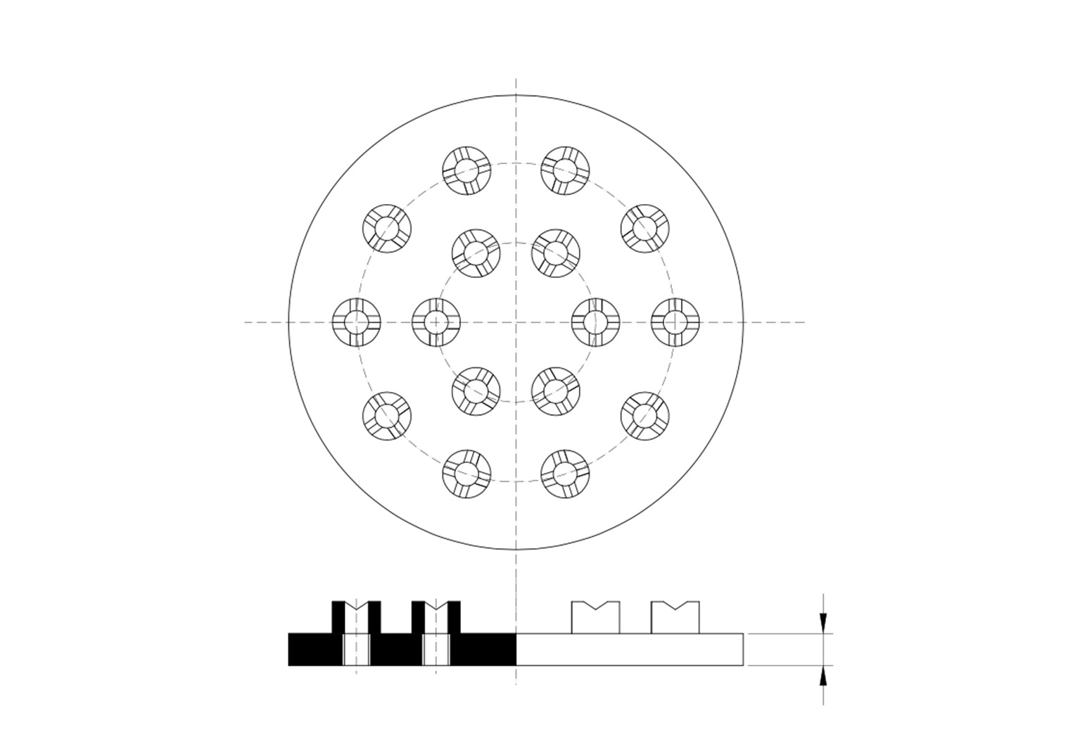
PTFE lined support ring
This adapter ring made of PTFE-lined steel is used for sustaining PTFE support grids, perforated plates, caps, etc. It is assembled by means of self-centering external bolts
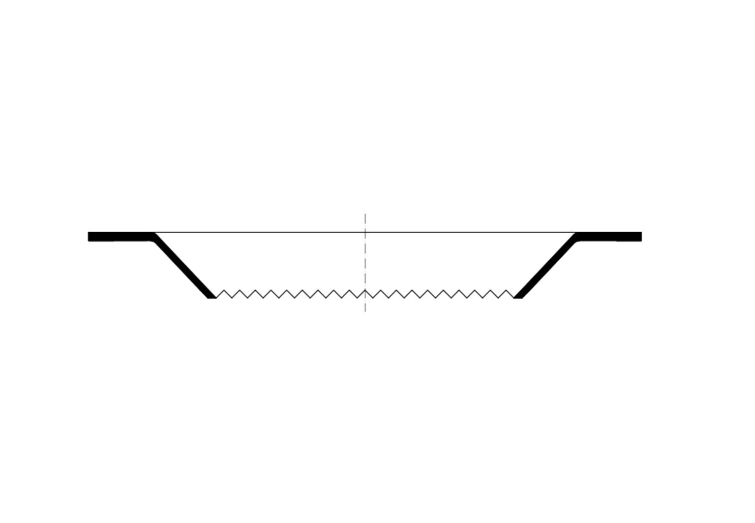
PTFE support grid
The support grid is entirely made of PTFE in various thicknesses, according to the maximum diameter and taper allowed. The support grid is also available in PTFE-lined Hastelloy steel. The grid is directly supported by the support ring (point 5). In alternative, it can be clamped between flanges. Recommended up to DN 600.
PTFE redistributor
In order to avoid medium distribution problems, redistributors should be installed at the distance of 2-3 m from each other, clamped between flanges. This will allow a correct redistribution of the process medium.
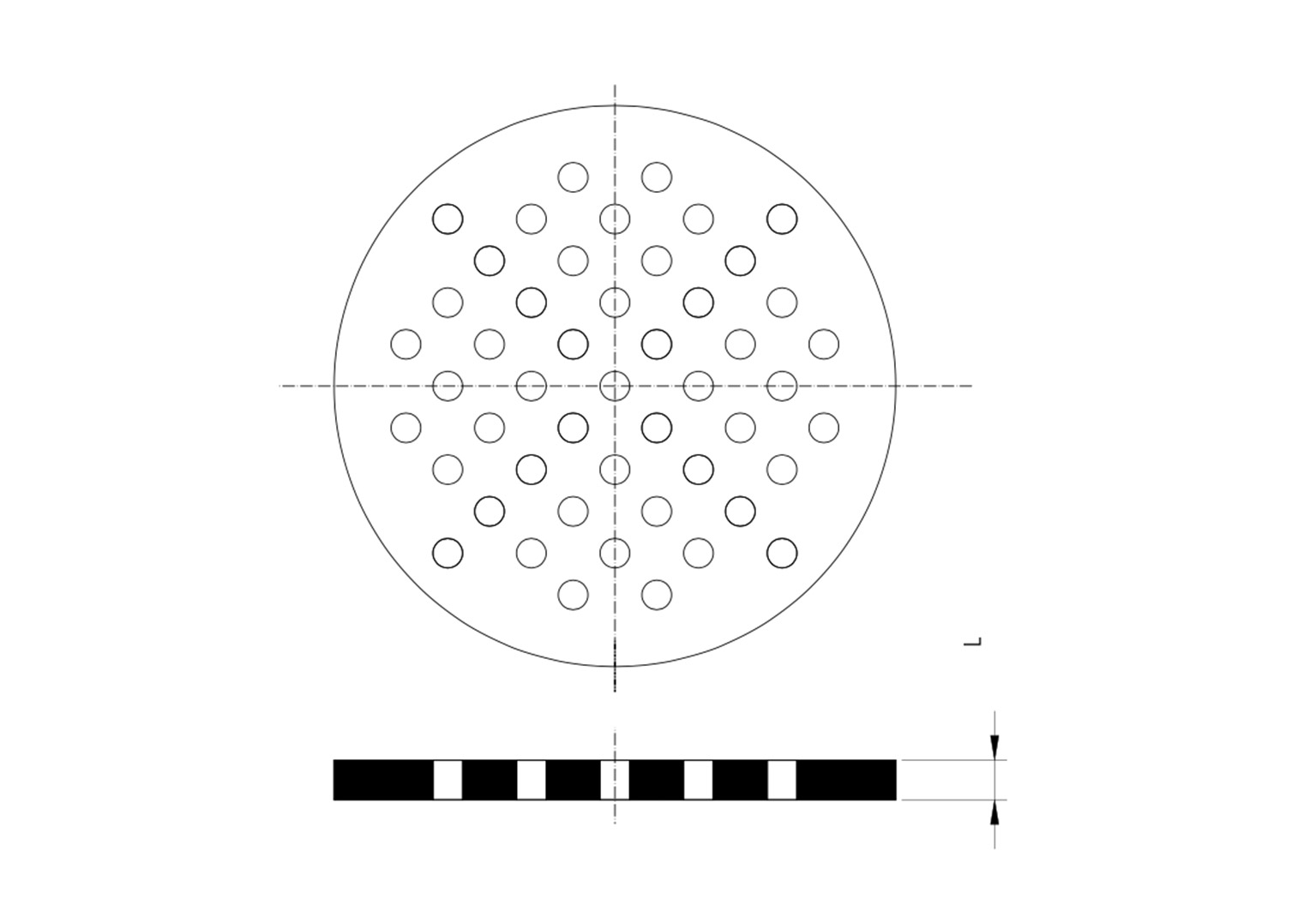
Distributor plate
Columns can be equipped with PTFE distributor plates that distribute the medium more uniformly.
VOLUME-DIMENSIONS TABLE
| Volume m3 |
DN |
H |
| 0,25 |
600/24” |
1200 |
| 0,5 |
800/32” |
1000 |
| 1 |
1200/48” |
900 |
| 1,5 |
1000/40” - 1400/56” |
2000* - 1000 |
| 2 |
1200/48” - 1500/60” |
1800* - 1100 |
| 3 |
1400/56” - 1500/60” |
2000* - 1800* |